|
|
So you want to check out if the book is worthwhile, but not exactly sure if you're ready to shell out the bucks to investigate it, hmmm? Well,
McGraw-Hill / Osbourne has graciously given us permission to post the first project, the "Symet".
What follows is the actual text and original photos from that chapter, minus a few superfluous graphics and the fancy formatting that the book offers. You'll be able to get an excellent idea of how we show you
how to build yourself practically the simplest of BEAM devices - the omnidirectional, solar-powered symmetrical Symet!
Project 1: The Symet: An Introduction to Solar-Powered Robotics
|
The BEAM Symet
|
|
We’re not going to attack a full robotics project until you’ve had some practice building a few simpler devices first, okay? Trust me, it’s still a fun project, and worth doing. Besides, while you’re too busy
having fun, we’ll sneak some useful info into your brain. It won’t hurt…much.
The Symet is a solar-powered BEAM device that is almost a robot. Because the device looks the same from several sides, we’ve taken the name from the word “Symmetrical,” but the extra “m” looks strange. “Symmet”—see? Doesn’t that look bizarre? This
device is about as simple and self-sufficient as they get. The solar cell powers the motor; the motor moves the device; and when it bumps into something, it tilts in a new direction and keeps on going. That’s the basic operation of the Symet.
|
The Solarengineengine: The Key to Solar-Powered Robotics
It’s time to cover the solar aspect of BEAM robotics. As mentioned earlier, we’ll use a solar cell to power this beastie. A tiny solar cell. At best, a solar cell provides only a small fraction of the power of a regular AA battery. In fact, of all the
solar energy falling on the solar cell (as light), less than 1/20 of the power gets turned into usable electricity. You will rarely be able to attach a solar cell to a motor and expect it to do anything. Fortunately, there is a family of
electronic circuits that will let you convert the weak power output of a solar cell to drive the loads of a small robot. A solarengine stores the trickle of power from the solar cell, and releases it in bursts of usable energy. That means
you have to wait a while until the power stores up to that usable level, but at least you’re getting some movement when it would be impossible without the solarengine. All solarengines work on the same principle:
- Store the energy.
- Decide when to dump the energy, then dump it.
- Do it again, and again, and again….
The first step (store the energy) is pretty straightforward. You attach the solar cell to a capacitor or a rechargeable battery, and let it trickle the power in. If you use a small capacitor (say, 1000µF), it will take only a few seconds of lamp light
to charge. If you’re using a supercap (1F), you’ll wait minutes; a rechargeable battery will take hours. The second step is a bit more complex. A circuit has several ways to decide when to dump the energy, just as you have several ways to select a flavor
of ice cream. Where you may use the qualities of flavor, color, or texture to satisfy your ice cream craving, a solarengine circuit can use time, voltage, or current to decide when it’s time to activate. When the decision has been made to send the power
out, a different part of the solarengine circuit blasts that power out to the rest of the robot, making it twitch, roll, walk, bleep, blink, or burp. The last step sounds simple, but it can cause headaches. It’s harder than it sounds to make sure a
circuit restarts over and over and over again. You know when some days you just don’t want to get out of bed? Well, sometimes electronics circuits misbehave that way too. Fortunately, this problem shouldn’t bother you much, as the circuits we’ll
use are tried, tested, and true.
Solarengine Types
Most solarengines use a voltage-based activation circuit. That means the circuit watches the volts stored in the capacitor to determine when to activate, the same way you watch a pressure gauge as you pump up a bicycle tire. When it’s high enough,
you know you’re good to go, and in the case of a solarengine, that means “time to dump power.” Voltage-based solarengines are pretty simple to build, and they are quite efficient, meaning the voltage-monitoring circuit eats very little of the power
coming in. This will be our solarengine of choice, and we’ll try several sub-flavors (like covered with chocolate sprinkles, or nuts, or strawberries…. Whups, wrong analogy!). The second major type of solarengine uses a built-in activation timer.
Timer-based solarengines will dump whatever power they’ve stored up over so-many seconds, whether the power-storage capacitor is 1/4 full, 1/2 full, or totally full for a while already. Like clockwork, they’ll dump whatever they have at regular
intervals. Solarengines of this type aren't much more complex than voltage-type solarengines, but they usually eat more power, as it takes energy to run the electronic timer accurately. |
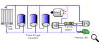
Figure 1: Flashing LED solarengine schematic
|
The third major type of solarengine watches the current flowing into the power storage capacitor to determine when to activate. It’s like when you’re inflating a
bicycle tire: when the air pump can’t push any more air into the tire, the airflow reduces to nothing. This sort of solarengine watches the flow of power into the capacitor, and when the solar cell can’t push any more power into it, it dumps the power.
This sort of circuit is somewhat complex, and not too many designs have been worth the difficulty of assembly. If perfected, this type of solarengine would give the best overall performance in all kind of light levels. |
Symet Behavior
|
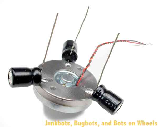
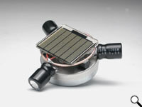
| The Symet sits on the motor shaft and the edges of two capacitors, naturally sitting off-center like a toy top when it’s not spinning (see Figure 7-1). When the
motor activates, it scoots the Symet forward a bit while the capacitors skid along. The neat thing about being symmetrical is that if it tilts over to a new side, the motor rotation will push the Symet in a new direction. The most important aspect of a
successful Symet is proper balance. Try to make it as balanced to the center as possible, and your Symet will work equally well on any side it happens to rest on. |
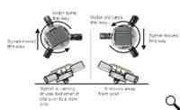
Figure 2: Symet motion explained
|
Symet Parts
|
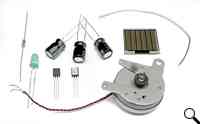
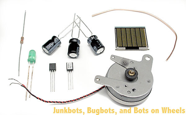
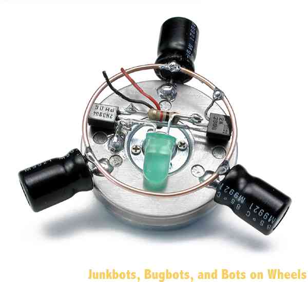
Figure 3: Symet parts, ready to go
|
Here’s where we get to the nitty-gritty of building a device. First, get parts.
 |
1 – Motor, the fatter and more pancake-like, the better. These rotate slower, but with more turning power. |
|
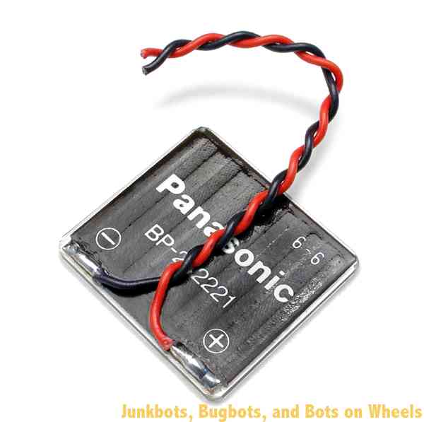
1 – solar cell, which must be able to put out a minimum of 3.0 volts. Measure it with a voltmeter if you’re not sure. |
|
3 – Similar capacitors, from 470µF to 4700µF, with 1000µF being darn-near ideal. |
|
1 – Resistor, 1k to 10k. You remember your resistor color codes, right? |
|
1 – 2N3904 or PN2222 transistor (either will do fine). |
|
1 – 2N3906 or PN2907 transistor (again, either will do fine). |
|
1 – Flashing LED. It must be a flashing or blinking LED—accept no substitutes. Get Active Components’ KLF-336-HD red 3-pack or Radio Shack’s 276-030/305/036 parts
if you can’t find this part. Red is preferable, as it will make your solarengine activate sooner than a green or yellow one, and it will be less prone to locking up (a bad thing). |
|
1 – Chunk of stiff structural wire; a copper paperclip is practically ideal. |
|
1 – Wee bit of electrical wire for making electrical connections to the solar cell. |
|
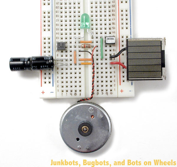
| Before you start actually soldering these parts together, it’s a good idea to make absolutely sure that they work together. It’s much easier to
figure out a bug in a “plug in and play” circuit than it is to implement all your recently learned “desoldering” techniques. It’s a plenty-good idea to get a hold of a breadboard, and temporarily hook up all the components you want to use, just to
make sure they work. For the Symet, take a look at Figure 7-3, and copy how all the parts were put in. When you shine a light on it (a 60-watt incandescent light is good), the motor should take no longer than ten seconds to pulse. |
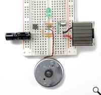
Figure 4: The breadboarded Symet circuit
|
The Robot Geek on What Can Go Wrong with Your FLED Solarengine
- The flashing LED is sensitive to light! Most semiconductors that emit light have the bizarre side effect that they are also sensitive to light. A flashing LED can lock up and stop working if it’s exposed to intense light (i.e., sunlight!), so keep
the flashing LED covered by the solar cell or by some black tape to ensure reliable operation. If you don’t, the Symet may pulse once, then stop working until you pass a shadow over it.
- If you hear a high-pitched whine from the motor (hold it up to your ear!), the solarengine is having trouble latching (turning on). Find a lower-value resistor and swap it into the solarengine.
- If there is no voltage in the power storage capacitor, you may have hooked up the solar cell backward to the circuit. This is a very common error.
- If your circuit charges your power storage capacitor up to only 0.6 volts and then stops, you most likely don’t have the motor hooked up to the solarengine. It needs the motor hooked up to charge.
- If you see the FLED actually flashing, then the solarengine resistor is too low for the solarengine to trigger the latch. Get a higher-value resistor, and swap it into the circuit. A typical trigger voltage for the FLED solarengine is about 3 volts
for the green FLED and 2.6 volts for the red FLED. If the measured voltage on the power storage capacitor is higher than this, then the FLED is probably not getting power. If you don’t have a multimeter to test this, you can do it with a single white or
blue LED. Just put this LED in parallel with the power storage capacitor (the long leg of the LED goes to capacitor ‘+’). If the LED lights up, then there is probably more than three volts in the capacitor.
- There is a slim chance that the solarengine can become saturated by having too much power. It will trigger once, then no more. No simple solution for this—just use a smaller solar cell.
- The flashing LED solarengine is sensitive to what motor is used. If it isn’t working with one motor, try a different one!
|
|
Building It!
|
|
The solarengine we’ll use with this particular project is a “flashing LED solarengine.” The two transistors and the resistor are arranged in what is called an “SCR latch”—which is the electronic name for a switch
that when turned on, stays on. The flashing LED (“FLED”) acts as the finger that flips the switch to turn it on, and once it’s on, it stays on until all the power has run out. What makes a FLED such a convenient trigger is that it has a tiny, tiny chip
inside that tries to make it light up every second, and every time it tries, it also tries to activate the switch circuit. Only when there’s enough power stored up in the main power storage capacitor is there enough juice to let the FLED kick the circuit
into operation. What makes the FLED particularly good at its job is the fact that when it’s in the off part of its cycle, it draws almost no power, which means more power gets stored up in the capacitors
Since there isn’t much to build as a body for the Symet, let’s start by building the solarengine, as it’s the trickiest bit to build. Everything else will be easy compared to this step, so let’s tackle it first. We’re going to take special effort with
the steps in this first project, showing you the graphic of what do to, and a picture of the step showing how it should actually look like after the step is performed. Subsequent projects will have just the photos showing the result of each step.
The transistors we’re using all have the same “pinout”. A pinout is the name and orientation of each lead coming out of the part. With our transistors, you can identify each of the leads by holding the transistor up, flat face towards you, pins
pointing downwards. From left to right, the pins are the “emitter”, the “base” and the “collector”. What do those names mean? They describe the flow of “electron holes” through the component. The emitter and collector are like the input and output of a
pipe, and the base is like the valve that controls the flow through the pipe. As for “electron holes”, that’s a term best looked up in a beginner’s guide to electronics, and is outside of the scope of this book.
|
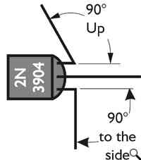
Figure 5: Forming the 2N3904 / PN2222 transistor leads
|
Take your 2N3904 / PN2222 transistor (remember, they do pretty much the same thing) and starting near the transistor body, bend it’s left lead (the emitter) 90° out to the
left side. Bend the right lead (the collector) 90° directly upwards, so it’s pointing up at you. Bending these leads will make it easier to solder other components on. |
| Take your 2N3906 or PN2907 transistor (again, they’re functionally the same, so either will do) and starting near the transistor body, bend the left lead (the emitter) 90°
out to the left side. Bend the middle leg (the base) 90° directly upwards, so it’s pointing up at you. Make sure your bends are looking like the ones in the figures! |
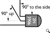
Figure 6: Forming the 2N3906 (or PN2907) transistor leg
|
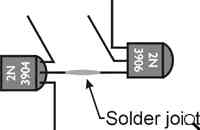
Figure 7: Joining the transistors together
|
This is the first really tricky part to free-forming the circuit. We’re going to solder the lead we didn’t modify from each transistor together. That’s the middle lead
(the base) of the 2N3904 / PN2222 and the right lead (the collector) of the 2N3906 / PN2907. This is a good time to have a set of helping hands, be it mechanical set our your friends. Arrange the transistors so they’re both face-up, and their leads are
overlapping so one almost totally covers the other. A bit of heat, a dab of solder, and they’ll turn into the core of your solarengine circuit. |
|
Adding the resistor isn’t terribly hard if you tilt the transistor assembly slightly away from you. It’s then a simple process to just lay the resistor across the two bent-up vertical legs, and to solder where the
resistor touches the transistor legs. Resistors don’t have a front or back, so whatever way you put it in is fine.
When you’re finished soldering the two sides of the resistor to the transistor uprights, you can trim off the portions of the resistor that poke past the solder joints. Also trim off the excess vertical lead from the 2N3904 / PN2222 collector, but
not from the other transistor vertical leg – we need that for attaching the FLED.
|
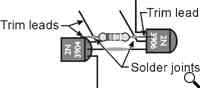
Figure 8: Adding the resistor to the mix, and trimming the leads
|
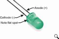
Figure 9: Identifying the cathode of the Flashing LED
|
We’re about to attach the flashing LED (FLED), but before we can do that, we need to identify the leads. Most LEDs have a flat spot near one of the legs which indicates the
“cathode”. The cathode is the lead where you hook up a negative power (‘-‘) or ground connection. The other side is called the “anode”, and hooks to a positive (‘+’) power connection. Locate the flat spot on the edge of the FLED, and make note of which
lead is closest to it. |
|
Take the FLED’s cathode and bend it so you can solder it to the left lead (the emitter) of the 2N3904 / PN2222 transistor. Then solder the other lead of the FLED to the upright middle lead (the base) of the 2N3906
/ PN2907 transistor, which is also soldered to the resistor.
Yeah, I know those directions seem clear as mud. Keep forging ahead and following the pictures, and you’ll be fine.
There—you’ve officially finished your first FLED solarengine circuit!
|
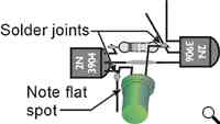
Figure 10: Finishing the core circuit with the flashing LED
|
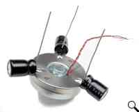
Figure 11: Soldering capacitors to the motor body
|
Time to find that big round shiny thing. Yes, we mean the motor, not your uncle’s balding head.
Let's add the power storage capacitors to the motor. Spaced equally and soldered to the motor, they will balance the Symet while storing the power for the solarengine. We’re doing this because the whole motor body will be used as one large electrical
connection in the next step, and the motor body will be like one large convenient wire! Your capacitors will most likely have polarity markings (remember that the striped side is negative), so make sure you’re connecting the capacitor’s negative
leg to the motor body. Bend the positive capacitor wires upward, just to get them out of the way, and clip the negative wires down so that they're just long enough to solder to the motor body. Soldering the capacitors on can be a bit tricky, because
motors don’t like to be soldered to. The metal body that covers the whole motor will have to be scuffed, sanded, or filed a bit to get through the dull surface to the shiny (solderable) metal below.
|
| Now we’ll mount the solarengine circuitry to the top middle of the motor. This is the place you will want to solder the left leg (the emitter) of the 2N3904 / PN2222
transistor. Solder the left leg down to the motor, remembering to first scuff / sand / file a spot to solder to on the motor body before soldering, and you’ll do just fine. Remember that since the motor is a large hunk of metal that absorbs lots of heat,
you’ll need to hold the soldering iron on somewhat longer before the solder will melt. |
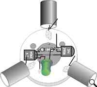
Figure 12: Attaching the solarengine circuit to the motor
|
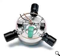
Figure 13: Soldering all the capacitor “+” leads and the left (emitter) lead of the 2N3906 / PN2907 transistor to the metal ring
|
So let’s recap: You’ve built a solarengine, attached it to the motor, and soldered three or four capacitors to the motor body. The next step is to finish making the electrical connections between all the “+” sides
of the capacitors with a wire loop. This is called wiring the capacitors in parallel, which is connecting all the “+” leads together and all the “–” leads together to effectively make one big capacitor. If you have three 1000µF capacitors wired in
parallel, they act as one big 3000µF capacitor.
This wire loop does more than just electrically connect the capacitors. It also acts as a bump-ring for the robot. When it bumps into something higher than the capacitor, it tips the Symet onto a new side, which makes it zoom off in a new
direction.
Form the loop into as nice as a round ring as you can. Be patient, and massage it into a loop with your fingertips, and you’ll be surprised how round you can make it. This task will be especially easy if you’re the type of person who regularly mangles
paperclips while talking on the telephone.
The next solder connection to make is from the left lead (the emitter) of the 2N3906 / PN2907 transistor to the same ring that the capacitor “+” legs all share.
|
|
Solder short lengths of wire to the solar cell, one to each pad. If possible, use the common practice of using a red wire for positive (+) and a black wire for negative (–). Many, many years of research have shown
that red wires conduct electricity best when attached to the positive terminal. If you don’t have red wire, use the next-brightest color—it won’t be as good as red wire, but it’ll do.
If you just read that last paragraph and wondered “Well, where do I have some red wire?” don’t worry about it—we’re pulling your leg. Color-coding your wiring is simply a good way to identify what wire carries what sort of signal. Red and black
are usually reserved for power wires.
Make absolutely sure you glue the wires down to the back of the solar cell after you’re done soldering them on. The connections to the solar cell are usually quite fragile and will rip right off if an ant trips over them. Well, they’re not
that fragile, but still, the connections are weak enough you should make sure to glue the wire down after soldering. Use hot glue, or even tape, but use something to secure the wires down. It’s a good procedure to follow on any solar cell.
|
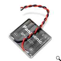
Figure 14: Soldering and gluing wires to the solar cell
|
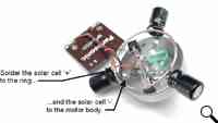
Figure 15: Soldering the solar cell to the Symet
|
You’re getting close to completion—just have to connect the motor and the solar cell, and your Symet should leap to life, do a song and dance, and throw confetti in the air. Either that, or it should occasionally
twitch, moving in one direction until it bumps into something.
Solder the red (+) wire from the solar cell to the connecting ring that joins all the capacitor “+” leads together. The black wire from the solar cell gets connected to the motor body. You can cheat a bit here, and solder this black wire to one of the
same spots you did earlier for the capacitor “–” connections.
|
| One of the motor wires gets soldered to the left lead (collector) of the 2N3904 / PN2222 transistor, and the other wire gets soldered to the capacitor connecting ring. It
doesn’t matter much which wire connects where, as it only will change the direction of motor rotation, and since this is a symmetrical robot, it doesn’t have any effect on how the Symet moves. |
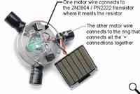
Figure 16: Soldering the motor wire connections
|
| If your Symet twitches after lying in the light for a few seconds, you’re ready to hot-glue the solar cell down to the top of the solarengine circuit. If it isn’t…well, it’s
time to go back to the troubleshooting section to see what could be the problem. With “freeform” circuits, you run the risk of making accidental electrical connections because there are so many bare wires close together. Make sure you don’t smoosh wires
or component leads together accidentally! |
Care and Feeding of Your Symet
|
|
Like most solar-powered BEAM critters, it’s best kept in a pen with a hard, flat surface and walls high enough to keep it contained. Symets are cool little devices that love to ricochet around their environment,
so they make great self-mobile plants for any robot display area.
If you find that your Symet isn’t quite tipping over enough to keep it out of trouble, try adding a second, larger ring (it doesn’t have to replace the one you already soldered in to the capacitors), and add a plastic sleeve to the motor shaft to add
traction. At your local electronics outlet, you’ll find neat material called heat-shrink tubing that once heated, shrinks down in size. This stuff is ideal for making friction sleeves on motors. In a pinch, cut a 1/4-inch slice of pencil
eraser and press it on the motor shaft as a friction wheel. Another technique is to use a blob of hot glue on the end of the motor shaft. It works well but tends to leave little plastic streaks on the surface of your robot pen.
|
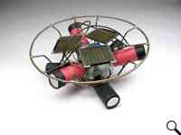
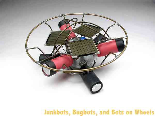
Figure 17: “Behemoth,” the monster Symet by Grant McKee
|
Symets can be built in many sizes and configurations. One of the largest ever built is “Behemoth,” by Grant McKee. This monster measures 14cm (5.5”) across, uses a
high-quality cassette deck motor, is powered by 16.5 volts from three solar cells and travels 15cm (6”) in a burst. McKee has plans for an even bigger that should be able to survive outdoors in a grassy backyard! |
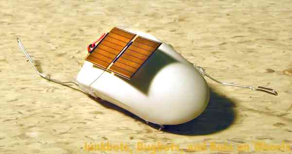
| Another interesting Symet was built at a BEAM workshop in 2002 by Adam and Zachary Aronson. This Symet was fit inside a computer mouse body, and has four coaster wheels on
the bottom. By having the drive motor in the middle pointing straight down and two coaster wheels on each side, this Symet can move forwards and backwards. The paperclip on each end of the mouse is designed to tilt the Symet to it’s other side, making it
scurry away from whatever hit the paperclip. |
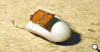
Figure 18: The Aronson mouse Symet
|
| Experiment with your devices—since you built it, you’re the best person to make modifications! |
|
|