|
|
Bug List
The following is a list of some known issues with the book. Hopefully, we'll be able to justify a second revision to the book, and fix them in that printing!
Schematic diagram misprints. Due to some inconsistencies between graphics formats, some of the schematics didn't reproduce so well. There's the occasional real error, but we're hoping not to find too many m ore of those! What follows are the
corrected versions. These are all sized so that if you print them out at 200DPI on your printer, you can cut them out and tape them on top of the offending graphic in the book.
Please note: These replacement images are only intended for legitimate book owners, and are still covered under the book's copyright.
Instead of downloading the image corrections individually, you can download a zipfile of the whole set.
 |
Page 5 - Chapter 1 (Welcome to the World of Simple Robotics), (Nov18 2002). Captions for Figure 1-2 and Figure 1-3 are reversed.
|
|
Page 34 - Chapter 3 (Identifying Electrical Bits), (Dec 2 2002). A picofarad is a million times smaller than a microfarad, not a thousand times. (Thanks to reader Mike
Richberg for this one)
|
|
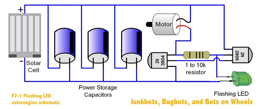
Page 95 - Chapter 7 (project 1: Symet), (Oct 15 2002). Figure 7-1: Flashing
LED solarengine schematic. Flashing LED didn't show up in image.
|
|
Page 95 - Chapter 7 (project 1: Symet), (Oct 15 2002). Figure 7-2: Symet
motion explained. Symet motion direction arrows went the wrong way.
|
|
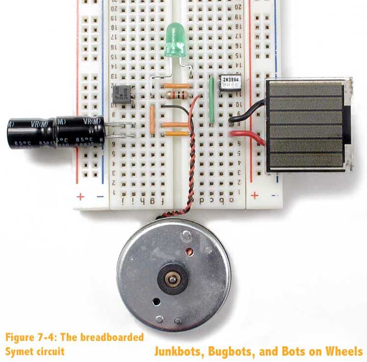
Page 97 - Chapter 7 (project 1: Symet), (Oct 15 2002). Figure 7-4: Symet
breadboarded. This image is simply too small in the book to be of any use to a roboticist who's trying to build it. Here's a larger copy.
|
|
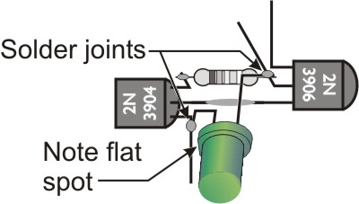
Page 101 - Chapter 7 (project 1: Symet), (Dec 2 2002). Figure 7-8: Adding the resistor to the mix, and trimming the
leads. The vector (line-art) graphic is wrong, wrong, wrong! The transistors are incorrectly connected. The photograph is correct.
|
|
Page 102 - Chapter 7 (project 1: Symet), (Dec 2 2002). Figure 7-10: Finishing the core circuit with the flashing LED.
The vector (line-art) graphic again is wrong, wrong, wrong! The transistors are incorrectly connected. The photograph is correct.
|
|
Page 103 - Chapter 7 (project 1: Symet), (Dec 2 2002). Figure 7-11: Soldering capacitors to the motor body (no replacement graphic). The "-" (minus sign) is missing
from the figure sentence "Solder the capacitor "-" leads to the top of the motor. Thanks to Jérôme Demers for spotting this error.
|
|
Page 107 - Chapter 7 (project 1: Symet), (Nov18 2002). Figure 7-16: Soldering
the motor wire connections. The right-side image shows a wire going to the motor body (wrong) when it should be going to capacitor ring. Thanks to bugfinder Alistair
|
|
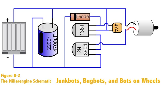
Page 113 - Chapter 8 (project 2: Solaroller), (Oct 15 2002). Figure 8-2: The
Millerengine schematic. Funky fuzziness abound!
|
|
Page 160 - Chapter 9 (project 3: The Herbie Photovore), (Dec 9 2002), Figure 9-30: Wiring up the eye sensors (no replacement graphic). The top middle text should
read "Light sensor cathode connects to "+" on LM386 pin 6..." (not pin 5). Thanks to Parth Shah for finding this buglet.
|
|
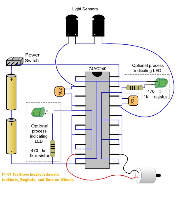
Page 175 - Chapter 10 (project 4: Headbot), (Oct 15 2002). Figure 10-7: The
Bicore headbot schematic. Missing / strange LED graphics
|
|
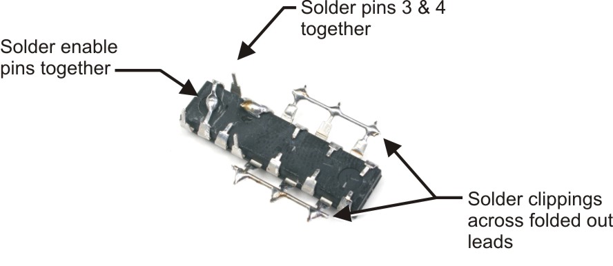
Page 184 - Chapter 10 (project 4: Headbot), (Dec 2 2002). Figure 10-18: Start of the 74AC240 pin soldering (no replacement graphic). The figure text is incorrect.
"Solder pins 17 and 18 together" should be "Solder pins 3 and 4 together." And ignore the spelling mistake "clippins," ok? Alistair's keen eyes found these bugs.
|
|
Page 185 - Chapter 10 (project 4: Headbot), (Dec 2 2002). Figure 10-20: Connecting the folded-in pins. The bottom right
pin (right at the bottom of the picture) shouldn't have been soldered to the rest of the pins folded inwards. This pin (pin 10) should be left solo. The text also repeats the error by stating 6, 8, and 10 should be connected, when pin 10 should
not be connected. Alistair strikes again (thx!).
|
|
Page 201 - Chapter 11 (project 5: Pendulum), (Oct 15 2002). Figure 11-2:
Magbot pendulum schematic. More missing LEDs. Darn things...
|
|
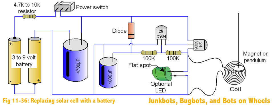
Page 230 - Chapter 11 (project 5: Pendulum), (Oct 15 2002). Figure 11-36:
Replacing the solar cell with a batter. Yet again, dang LEDs causing havoc.
|
|
Page 246 - Chapter 12 (project 6: Minisumo), (Nov18 2002). "10x10 cm (2.54" x 2.54")" is incorrect. 10x10cm is actually 3.94" x 3.94". Thanks to Eric Stewart and Jerome
Demers for this one.
|
|
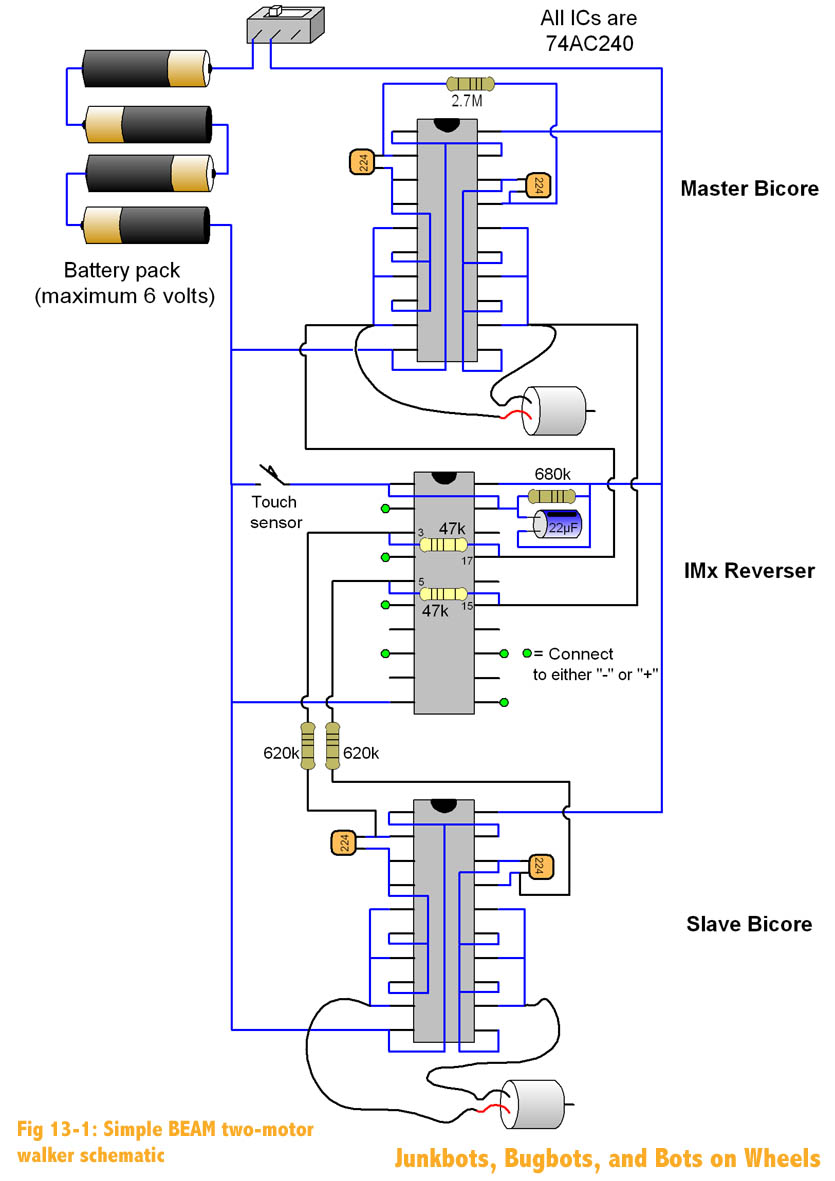
Page 278 - Chapter 13 (project 13: Walker), (Oct 15 2002). Figure 13-1:
Simple BEAM two-motor walker schematic. Wire overlap is unclear on IMx.
|
|
Page 296 - Chapter 13 (project 13: Walker), (Dec 5 2002). Figure 13-16: Bicore "deadbug" leg forming and soldering (no replacement graphic). The bottom right text
string should read "Group solder pins 3, 4, 6, 8 and 11, 13, 15, 18 together." It was 2, 4, 6 ... (Thanks to Dan Chiodo)
|
|
Page 321 - Chapter 13 (project 13: Walker), (Nov18 2002). Figure 13-50. It's a repeat of the graphic on page 294. Bizarre. New graphic to eventually show up.
|
|
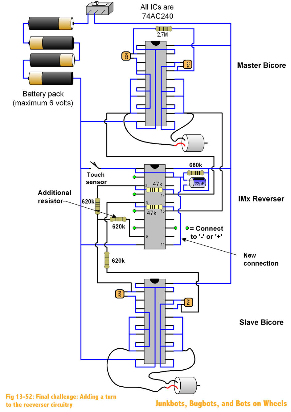
Page 323 - Chapter 13 (project 13: Walker), (Oct 15 2002). Figure 13-52: Final
challenge: Adding a turn to the reverser circuitry. The "additional resistor" value and capacitor values didn't print properly.
|
|
Page 323 - Chapter 13 (project 13: Walker), (Nov18 2002). Figure 13-52: Final
challenge: Adding a turn to the reverser circuitry. Arrgh! Would you believe that the previous correction still wasn't 100% right? Thanks again to Jerome Demers for this one.
|
|
Page 328 - Chapter 13 (project 13: Walker), (Dec 5 2002). Figure 14-2: A minimal high-gain one-way motor driver, negative signal trigger (no replacement graphic).
The top right transistor labeled "2N3906" has the arrow pointing the wrong way, as it should be inwards. (Thanks to Dan Chiodo). Interesting side-note: Put a 2N3904 in this location instead with emitter/collector reversed, and you have an "active-high"
driver. |
|
|
|
|

