|
Secret
Project: The BEAMAnt- Light Seeking Reversing Robot
|
|
BEAMAnts are one of the oldest autonomous BEAM critters.
The original BEAMAnts used the ancient HBS engine of BEAM god lore, and
although they did their job well, they were slow and tended to get their
long power-generating photodiode necks broken by turbots. The next major
improvement in the BEAMAnt genus was the Photopopper, which does
essentially the same thing as the original "BanjoBug BEAMAnt",
but with newer technology that made it faster and easier to build.
The
successor to Photopopper technology is developing out of what is called a
Unicore type circuit, allowing the creation of a reversing photovore,
which is what powers the BEAMAnt 6.0 series robot and the BEAMAnt we will
be building using a 9V battery for power.
Battery powered?
Yes, while it is true that BEAMAnts have traditionally
been solar powered, this battery powered device saves the trouble of a
solarengine as well as finding suitable capacitors and solarcells. The GM2
and GM3 style motors used have less than stellar performance under solar
power. However, with reasonably efficient motors and a few extra
components this project can be solar powered.
|

The first BEAMAnts, the "Banjo Bugs"
-
- The first BEAMAnts were powered by a string of solar cell
photodiodes and used a HBS (Happy Birthday Singer) for the
"brain".
-
-
-
-
-
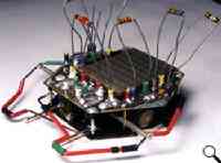
An inspiring original: Mark Tilden's BEAMAnt 6.0
These use very efficient micro gearmotors, they can run full time using
a SC3733!!
|
|
|
|
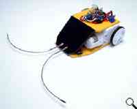
F01- Complete BEAMAnt This project is not for the
faint of heart as the free-forming gets somewhat involved. You may want to
practice on simpler book projects such as the Symet or Herbie first or
simplify construction using the solarbotics BEP boards. If
you want to jump in head first, no one is going to stop you (or be able to
throw you a life-line either!).
|
The
BEAMAnt Explained:
So before we get knee-deep in building, let's get some background
theory which will be helpful later if and when you need to troubleshoot
your BEAMAnt.
The core of this circuit is the phototropic Bicore, composed of a pair
of inverters, a pair of capacitors, and a pair of photodiodes. We won't go
into great detail on the principles of Bicore operation (there's some
excellent descriptions on the 'net already - Googlesearch them up!). All
that you need to know is that the output duty cycle will vary as the light
level between the eyes changes. This behavior is what controls the Headbot
project in chapter 10 of the book
For this project we want a bit more control over the signals being sent
to the motors, so the output of the phototropic Bicore is fed into another
Bicore, called the filter Bicore. The filter Bicore can be used to change
the response time of the motors and provide an isolation stage to keep the
BEAMAnt from locking up when in reverse. The filter Bicore takes the
incoming signal from the phototropic Bicore and will output a logic high
or low, depending on the duty cycle received. Like all Bicores, when one
side is high the other side must be low, meaning that only one motor will
be on at a time.
What these two stages control is the actual phototropism of the BEAMAnt,
and if set up properly, it will always turn towards the brightest source
of light. We could stop here and have a light seeking robot, which is all
fine and dandy until it bumps into something. Perhaps we'll add some kind
of obstacle avoidance such as tactile sensors...
Getting the BEAMAnt to reverse is simple. By reversing the polarity to
the unused side of the motors, we get reverse motion. It also doesn't do
much good to just reverse when the tactile is actually hitting something,
so having a "time-out" circuit attached to the sensor greatly
increases its effectiveness. For simplicity sake, lets just look at one of
the two reverser circuits. Each reverser consists of a inverter, resistor,
capacitor and a switch. When the switch closes, the capacitor charges up
to a logic "high" level, where the signal is then inverted by
the inverter to logic "low", causing the reverse to happen. When
the sensor is released, the resistor slowly discharges the capacitor until
the inverter reverses to it's original state, making the motor go forward
again.
There is only one more issue to address: the BEAMAnt has a tendency to
stall if the lighting conditions are right and it tries to reverse.
Stalling happens because the circuit will turn on only one motor when
turning towards a light source and due to the reverse sensor, it will also
try to invert that signal going to the motor. To fix this, the reverser
will force the circuit to oscillate giving both motors a chance to move.
So in short:
- The phototropic Bicore outputs a duty cycle dependant on light level
differences between the eyes.
- The filter Bicore will provide a logic high or low to the motor
driver depending on the duty cycle received from the phototropic Bicore
- If a tactile is hit, this will invert one side of the signal sent to
the motor driver reversing the motor, also this will force the duty
cycle of the filter Bicore to around 50%
- The motor driver receives signals from the reverser as well as the
filter Bicore and amplifies these signals going to the motors.
|
The Circuit Diagrams:
|
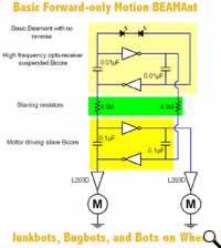
This is the schematic of the original basic BEAMAnt with no reverse
capability,
which will work as a basic light seeker or line follower.
PDF Version
| 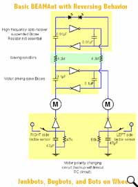
The basic BEAMAnt circuit with a reverse by adding on
additional buffers on the ground side of the motors.
PDF Version
|
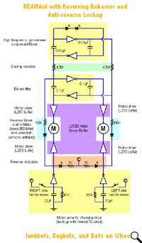
This is an even more advanced BEAMAnt circuit with the "reverse
process kill" fix, showing motor buffering via a L293 motor
driver chip, pretty much what we'll be building but without the reverse
indication LED's.
PDF Version
| 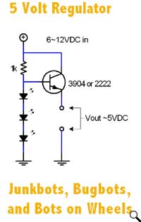
Need a 5V regulator, and can't find a 7805? This one suits our
purposes nicely...
PDF Version
|
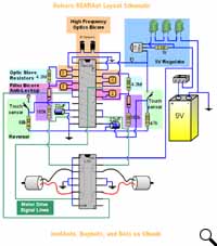
And the star of the show, the wiring schematic we'll be using to
build a BEAMAnt with positive
phototropism, reverse, and anti-lockup features.
PDF
Version
|
BEAMAnt Parts
|
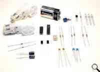
F02 - BEAMAnt Parts
|
Here are the basic components to building a BEAMAnt:
 | 2 - Motors,
Gearmotors are preferable, aim for a gear ratio of 4:1 up to 300:1 |
 | 1 - 74AC240, DIP package |
 | 1 - L293D, motor driver chip |
 | 7 - Resistors, Assorted values more on this later |
 | 2 - 0.01µF capacitors, label on capacitor "103" |
 | 2 - 0.1µF capacitors, label on capacitors "104" |
 | 2 - 22µF capacitors, label on capacitors 22uF |
 | 2 - Photodiodes (can also be substituted with CDS cells with minor
circuit modifications) |
 | 1 - 9V battery, rechargeable or alkaline (avoid carbon cell
batteries!) |
The following are for the discrete voltage regulator, you could just
use a 7805 voltage regulator:
 | 1 - 2N3904 or PN2222, NPN type transistor |
 | 3 - LED's, use green or yellow if possible |
 | 1 - 1K resistor |
The following are components for mechanical construction (not shown):
 | 1 - Sintra, wood, lexan, sheet metal or whatever you can use to make
a body, we used Sintra, its light easy to work with and glues very
well. |
 | 2 - 1" lengths of 1/8" Heatshrink |
 | 2 - 2" lengths of spring (we used Solarbotics TACT1 spring) |
 | 2 - 1" lengths of 1/8" OD diameter brass tube |
|
Got Breadboard?
Before you jump right into soldering you may want to breadboard the
circuit to make sure it works. You may also want to run wires out to the
motors to see if they have a reasonable speed at whatever voltage you
decide to run them at (between 2V to 18V).
We recommend building the circuit up in stages on the breadboard. Start
with the motor driver, add the phototropic Bicore, then add the filter Bicore
and last add the reverser.
If you have the extra parts, leave the working breadboard circuit
together, and use it as a model to build the freeform version.
|
So what do the resistors do?
The slave resistors are 4.3M by default, as this value goes down the
response time of the motors get quicker, this means that it wags back and
forth less. Its up to you how much wag there is, if the resistor value is
low enough the wag basically disappears. The reverse timing resistors
controls how long the BEAMAnt will turn, default values are 47K and 68K.
Its a good idea to select slightly different values for backup timing
because if both sensors get hit at the same time you don't want the backup
to time out at the same time and charge strait forward again..
|
The Robot Geek on What Go Wrong with Your BEAMAnt circuit
 | Be very careful with the voltage regulator circuit. It must be
in place before you attach power, and we highly recommend
testing it before use. If the 74AC240 chip gets a full 9V it
will fry and must be replaced! Don't worry about the L293 chip
as it can run up to 36V. |
 | With high current motors, you may run into problems with the
internal resistance of the battery. Alkalines are best and
carbon cells are near useless. Signs of this are that the motors
take a bit of time to get up to full speed. |
 | Don't forget to put the resistors in before you test the
BEAMAnt - it won't do much without them. |
 | If you have a multimeter, use it to test the photo Bicore. Set
the meter to measure at least 5V DC, and with equal lighting on
the photodiodes you should measure half the supply voltage at
the photo Bicore output (around 2.5V). As you vary the light
level on the eyes you can measure the average voltage as the
output. |
|
|
Start Building It!
|
|
|
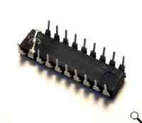
F03 - Solder Enables together |
Take the 74AC240 chip and fold the two enable
pins together and solder, these are pins 1 and 19. |
| Next add the pair of 0.01µF capacitors and
the pair of 0.1µF capacitors. One 0.01µF capacitors soldered between pins 2 and 3
the other 0.01µF capacitors between pins 17 and 18. The 0.1µF capacitor is soldered
between pins 4 and 5 the other 0.1µF capacitor goes between pins 15 and 16. For
a color reference the blue capacitors are the 0.01µF capacitors.
The 0.01µF capacitors are used for the phototropic Bicore, they need to run
at a relatively high frequency as compared to the filter Bicore.
|
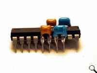
F04 - Solder capacitors on chip |
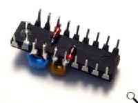
F05 - Solder diodes |
This next step is probably the
hardest part in free-forming. Its a bit tight but you need to solder the
diode anodes (side opposite of bar) to the inputs of the filter Bicore ( pins 4 and
15). Clip the excess lead but leave just enough to
solder another lead to. |
Next add the 100K
resistors between the diodes and the outputs of the reverser.
For ease of free-forming we chose to use the bottom two inverters for the
reverse timing. This makes the inputs to the reversers pins 8 and 13 and
the outputs pins 12 and 9 respectively.
You could put sockets in place of these resistors but they only play a
small part in the overall behavior and aren't really worth the trouble of
adding sockets.
|
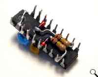
F06 - add the 100K resistors
|
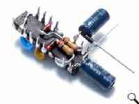
F08 - Adding the 22µF capacitors
|
Now we add the 22µF capacitors.
These capacitor are polarity sensitive, with the negative lead being the the shorter lead or the one
nearest the side with the
stripe on the capacitor body. Solder this negative lead to ground (pin
11), and the other pin to pin 8. Solder the other 22µF capacitor to pin 13 and
ground (stripe going to ground, remember?).
During this step its a good idea to tie those floating inputs to a
convenient output. The fastest way of doing this is to run a small solder
bridge between pins 12 and 13 and another bridge between pins 5 and 6. This will
keep the floating inputs from picking up stray signals and causing erratic
behavior later on.
|
| Its a very good idea to add sockets
so that the behavior of the BEAMAnt can be "edited" later.
Sockets go on pins 3,4,8,10(two go on pin 10),11,15, and 18.
|
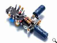
F09 - Adding sockets in place of resistors
|
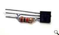
F11 - Solder Resistor to transistor
|
Now that the BEAMAnt circuit is
basically finished, lets move on to building the voltage regulator. Before
we get too involved in free-forming this regulator, keep in mind that you
can substitute in a common 7805 voltage regulator and save yourself a
bit of work.
The first step is to solder a 1K resistor between the Base and
Collector of the 3904. Looking at the flat side towards you, pins pointing
down, those are pins 2 and 3. This
resistor limits the current provided to the voltage reference generated by
three series LED's. |
| To provide a voltage reference, we
need to solder 3 LEDs in series. We found that green LEDs are a very
close 5V reference. Actual measured regulated voltage from a 9V supply was
4.94V. |
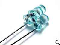
F12 - soldering LED's together
|
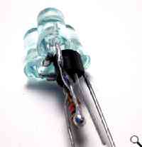
F13 - Adding the LED assembly to the transistor
|
Connect the Anode of the LED assembly to the Base of the transistor.
That's it for the voltage regulator.
Pinout is as follows:
 | The 3904 Collector is voltage input (6V
- 12V) |
 | The LED cathode is
connected to ground |
 | The 3904 Emitter is the
regulated voltage out (5V) |
If you have a multimeter I
highly recommend giving this circuit a test, as if this fails you could
fry your 74AC240 chip. The output voltage can be anywhere between 4 to 6
volts and still drive the 74AC240 chip with no problems.
|
| There is minimal free-forming to do
on the motor driver - simply solder all of the ground lines together.
Those are
pins 4,5,12,13.
You will need to run a spare lead across the middle of the
chip to connect pair 4,5 and 12,13.
|
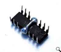
F14 - Motor driver
|

F15 - Attaching Voltage reg to 74AC240
|
Now we need to attach the voltage
regulator to the 74AC240 chip.
The 3904 Emitter is connected to pin 20 on
the 74AC240.
The Cathode on the LED assemble is connected to the enables
(pin 19 and pin 1). For now, the Collector of the 3904 is left connected to
nothing.
|
| Now that the voltage regulator is
in place we need to attach all of the grounds together on the chip.
The
black wire here connects the enables to ground. This means that pins 1,11,19
and the LED's Cathode are all connected together.
|
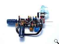
F16 - attaching grounds together on the 74AC240
|
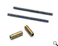
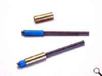
F17, 18 - Sensor construction |
Brains are pretty much done, so
it's time for some mechanical construction! Let's start by building the tactile sensors for the
BEAMAnt
Shown here are two pieces of spring tubing and two pieces of brass tubing.
The springs fit loosely inside the brass tubes.
Keep in mind that this is
just one of many different tactile sensors that can be used. Use whatever
type of switches suit your fancy, or simply order a Solarbotics TACT2 kit.
The sensors we're building here are more robust, and will put up with much
more abuse than a TACT2 sensor.
Take a bit of heat shrink and fit it over the spring and heat it so it
shrinks down. This heat
shrink should snugly fit inside the tube, if not either add a layer of heat shrink
or squish down the tubing a bit. |
| Now to start the construction of
the body. The 3mm yellow plate here is going to be the bottom. We won't
give you dimensions, as the shape will depend on your motors/wheels. Want
exact dimensions? Contact us, and let us know - if demand warrants it,
we'll put a plan together.
The blue square
with the smaller white square are spacers so that the metal motor shaft
does not hit the battery. The 6mm white Sintra blocks on top provide space
between the top plate and the battery.
|
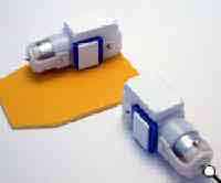
F19A - Motors on Sintra
|
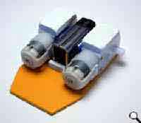
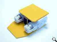
F19B,C - Add battery and top Sintra plate |
The top figure shows a small white Sintra
block that stops the battery from going too far into the body. Also note
how the battery fits nicely between the two motors, this makes it easy to
replace when it dies.
The bottom picture shows a 3mm yellow Sintra plate used to cover the top
and provide an open spot to mount the BEAMAnt brain. |
| Here all of the body pieces placed
together, this gives a good idea of how it will look when its done.
Nothing here is glued down yet, we still need to take it apart and wire it
up. |
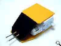
F19D - Front sensor plate
|
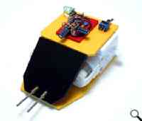
F19E - fitting the brain on the body + switch + tactiles
|
It's time to put the freeform brain
on the body.
You may notice that there is a the black front plate
with the sensors and the power switch. These were just placed there to see
how everything fit together, nothing is glued down yet. The BEAMAnt freeform is mounted on the red piece of
Sintra on top.
|
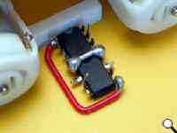
F20 - placing and wiring the L293D
|
With the black front plate removed,
place the
L293D chip between the motors and run a wire between the logic supply Vcc
and the power supply Vcc. As you probably guessed that's the red wire
connecting pins 8 and 16.
There is also a bit of pin forming here, the outputs to the motors are
clipped a bit to try and keep things clear. |
| Attach the output of the L293D to
the motors. Pins 3 and 6 are connected to the right motors and pins 11 and
14 are connected to the left motor. The blue wires connect the L293D
outputs to the motors. |
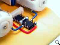
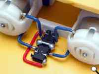
F21, 22 - Hooking L293D to motors
|
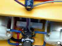
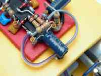
F23, 24 - Inputs of motor driver
|
Attach four wires to the motor drivers
and run them back to near the BEAMAnt brains.
The grey wire connects to pin 2, and the purple wire connects to pin 15 on the L293D chip.
On the BEAMAnt brains, the grey wire connects to
pin 9 and purple wire connects to pin 12, which are the outputs from the reverser
portion of the Unicore circuit.
We
highly recommend leaving these wires a bit long just in case you need to
reverse them later.
|
| Attach wires between the other pair
of inputs and outputs of the BEAMAnt circuit.
Its a good thing these wires
were a bit long they needed to be switched after testing. It worked out
that the tactile fix was holding the wrong side low, this is easy to fix
just swap the motor leads. The outermost gray
and purple wires needed to be swapped! Look at F33 to see this.
|
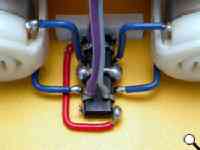
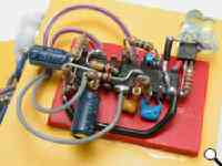
F25, 26 attaching the other motor driver inputs
|
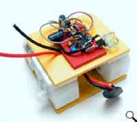
F27 - adding the battery snap
|
Now to install the battery pack
clip. Feel free
to drill holes in the Sintra to make wiring more convenient. |
| The + on the battery snap goes to
the middle pin on the switch. Choose one of the side pins to be where you
want to connect all the + connections to.
The red wire trailing to the left of the switch
is where the 3904 Collector we left is now attached (the input to the
voltage regulator).
The red wire trailing downwards is connected to the
red wire on the L293D motor driver which passes a full 9V directly to the motor
driver. That small blue Sintra block to the right of the switch is just
used to reinforce the switch mount.
|
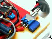
F28 - Wire power to switch
|
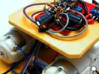
F29 - Wire all grounds
|
The black wire from the battery snap is wired to
pin 11 on the 74AC240 chip.
Run a wire from pin 11 on the 74AC240 chip to the ground pins on the
L293 chip. This will attach all of the grounds together. |
| The red wire going to the motor
driver goes to the same pin on the switch the "voltage in" on the
regulator is connected to. When the switch is flipped the motor driver
will get a full 9V.
Don't try and run the motor driver through the voltage
regulator!
|
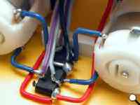
F30 - Power to the motor driver
|
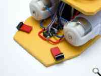
F31 - Adding the eyes
|
Mount the eyes in the body pointed
outwards at an eye angle anywhere between 0 and 180 degrees.
These eyes are roughly at 150 degrees from each other.
Feel free to
experiment with eye angles, as narrow ones will give you great
"lock-on" when light is found, and wide ones give a better
"search for light" capability.
|
| Solder a wire between the two
Cathodes (the side with the notch - green wire) |
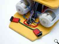
F32 - Solder a wire between the eyes
|
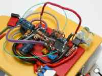
F33 - Wiring eyes to the circuit
|
The two anodes of the eyes get soldered to the
inputs to the first Bicore (pins 2 and 17), these are the thin green wires. This is an important stage:
When powered up, the BEAMAnt should
be phototropic or photophobic. If your getting a behavior opposite to what
you want just reverse where the eyes are connected to the Bicore inputs.
The red wire sticking up was used to test if the tactile sensors worked
properly. Do this by touching pin 20 to either pin 8 or pin 11, the motors
should reverse. In this picture there is no time limiting resistors for
the reverse so it will reverse forever. If you closely at the purple and
gray wire you will notice that they have been swaped as compared to F26. |
| Back to preparing the sensors!
Solder a wire across the two brass
tubes (red wire) and one wire each to the springs inside the tubes (white wires).
Solder a long red wire to the brass tubes, If you haven't caught on
already, the basic wiring rule is red wires are connected to positive (in this case +5V) and black
wires to ground.
|
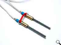
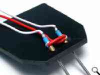
F34, 35 - Wiring the Tactile sensors
|
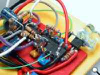
F36 - Wire sensors to the Circuit |
Wire in the tactile sensors, one wire goes to
pin 8 and the other goes to pin 11. Just take a guess at how to hook the
white wires up you have a 50% chance of being right...
Unless you want your
BEAMAnt to act as a sumo robot, you want it to turn away from the
obstacle touched.
If it does charge into object, simply switch
where the wires are connected. The red wire we see looping up is from the
tactiles, this is connected to the brass tubes and goes to pin 20 on the
74AC240 chip.
|
| That's just about it, at this stage
you should have a fully functional BEAMAnt. check to make sure that the
tactiles actually turn the BEAMAnt away from obstacles and not into them. |
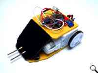
F37 - Almost done |
|
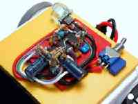
F38 - Cleanup
|
Now that your sure you have all the sensors and
motors going in the right direction its time to clean up the wiring. This
step is optional but sure helps with the Aesthetic part of BEAM. |
| Now just add some
stiff wire extensions to the sensors bend them however you like and your
BEAMAnt is finished! |

F01 - Complete |
|
Care and Feeding of Your BEAMAnt
|
The BEAMAnt works best with a hard, flat surface with walls high enough to
trigger the tactile sensors. It's also not that difficult to incorporate an edge
detector (think: trigger both sensors simultaneously). Combine that with crossing the
tactile sensors and you have a phototropic mini-sumo (particularly handy
if your opponent has a 100 watt bulb strapped to his head).
|
What about the pair of unused inverters?
|
You may have noticed that there are still two free inverters that we did not use, these
inverters can be used for a variety of extra behaviors such as:
 | Random reversing time |
 | Reverse then turn when a tactile is hit |
 | A break free pulse to free the BEAMAnt if one motor gets stuck |
 | Dark
illumination using a single inverter so if it gets dark headlights turn on |
 | Push
button turn on/off
- Extra LED
indicator buffers |
|
| Experiment with your devices—since you
built it, you’re the best person to make modifications! |
| Problems or questions? E-mail us!
 Have found the "Secret Special Project!"
|
|
|


